Fuse/relay panel description
2C_InstrumentPanelFuseLabel
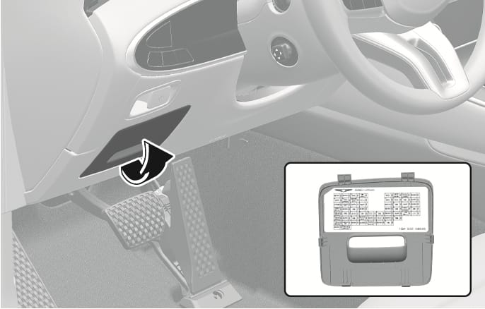
Inside the fuse panel cover, you can find the panel label describing fuse names and ratings.
Not all fuse panel descriptions in this manual may be applicable to your vehicle. When you inspect the fuse panel on your vehicle, refer to the fuse panel label.
1C_InstrumentPanelFuseLabel_1
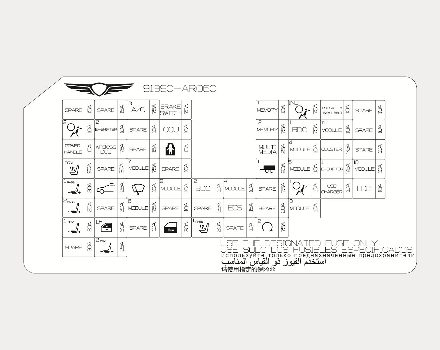
Instrument panel fuse panel
|
Fuse Name |
Symbol |
Fuse Rating |
Circuit Protected |
|
A/C3 |
|
7.5 A |
E/R Junction Block (RLY2,RLY3, RLY4), Front/ Rear A/C Controller, A/C Control Module, A/C PM Sensor, Incar Temperature Sensor |
|
BRAKE SWITCH |
|
7.5 A |
Stop Lamp Switch, BDC |
|
MEMORY1 |
|
10 A |
BDC, Console Mood Lamp Unit, Mood Lamp Unit, CDCU, Driver/Passenger Door Mood Lamp, Front Monitor, Security Indicator, ETCS Unit, Built-In Cam Unit, Smart Phone Wireless Charger, Driver/Passenger Door Mood Lamp #1/2, Rear Door Mood Lamp LH/RH #1/2,Rear Radar LH, ADAS Unit (Parking) |
|
A/BAG IND |
|
7.5 A |
Overhead Console Assembly |
|
PRESAFETY SEAT BELT1 |
|
10 A |
Pre-Active Seat Belt Unit |
|
AIR BAG2 |
|
10 A |
SRS Control Module |
|
E-SHIFTER2 |
|
10 A |
Electronic ATM Shift Lever Dial |
|
CCU |
|
10 A |
CCU |
|
MEMORY2 |
|
7.5 A |
Front/Rear A/C Controller, Front Console Keyboard, A/C Control Module, Head-Up Display |
|
BDC1 |
|
7.5 A |
BDC, BMS Control Module |
|
MODULE11 |
|
10 A |
CCU, DCU, Stop Lamp Switch |
|
POWER HANDLE |
|
15 A |
Steering Tilt & Telescopic Unit |
|
wireless DCU |
|
7.5 A |
DCU |
|
CHILD LOCK |
|
15 A |
Rear Door Lock Actuator LH/RH |
|
MULTI MEDIA |
|
25 A |
Low DC-DC Converter, CCIC Head Unit |
|
MODULE4 |
|
10 A |
Smart Phone Wireless Charger, A/C Control Module, AMP, Low DC-DC Converter, Data Link Connector, ICC Unit, Built-In Cam Unit, CCIC Head Unit, UVC Lamp Unit, Electro Chromic Mirror, Crash Pad Switch, Overhead Console, Lamp, Front/ Rear A/C Controller, Front Console Switch, Low DC-DC Converter (AMP),Driver/Passenger Seat Module |
|
CLUSTER |
|
7.5 A |
Head-Up Display, Front Monitor |
|
S/HEATER DRV |
|
20 A |
Driver Power Seat Module |
|
MODULE7 |
|
7.5 A |
12V Lithium Auxiliary Battery, AC Inverter, AC Inverter Outlet, Head Lamp LH/RH |
|
TRAILER1 |
|
20 A |
Trailer Connector |
|
MODULE5 |
|
10 A |
Driver Door Module, Multifunction Switch |
|
E-SHIFTER1 |
|
7.5 A |
Electronic ATM Shift Lever Dial |
|
MODULE10 |
|
10 A |
Front Monitor, CCU, Low DC-DC Converter, DCU, Built-In Cam Unit, Armrest Lamp, Electronic ATM Shift Lever Dial, CCIC Head Unit, BDC, Front Console Keyboard, Emergency Call Switch, ADAS Unit (Parking), E/R Sub Junction Block (RLY. 9), AMP, Low DC-DC Converter (AMP) |
|
P/SEAT PASS1 |
|
30 A |
Passenger Power Seat Switch, Passenger Power Seat Module |
|
SUNROOF |
|
25 A |
Sunroof Control Unit (Master) |
|
WIPER |
|
10 A |
Multifunction Switch, Rear Junction Block (Rear Wiper Relay) |
|
MODULE9 |
|
10 A |
Data Link Connector, Steering Tilt & Telescopic Unit, Driver/ Passenger Power Outside Mirror, Driver/ Passenger Power Seat Module, Driver/ Passenger Power Seat Switch, Power Tailgate Unit, Driver Door Module, TMS |
|
BDC2 |
|
10 A |
BDC, Ignition Switch, Bluetooth Unit #1 (Master), Bluetooth Unit #2 (Slave), Driver/Passenger Door Outside Handle, Rear Door Outside Handle LH/RH,UWB Antenna (Front LH/RH, Rear LH/RH) |
|
MODULE8 |
|
10 A |
Multifunction Switch, Rain Sensor, ICC Unit |
|
AIR BAG1 |
|
10 A |
SRS Control Module |
|
USB CHARGER |
|
10 A |
Rear USB Charger |
|
LDC |
|
10 A |
Front/Rear Radar LH/RH, Smart Phone Wireless Charger, Front/Rear A/C Controller, ADAS (Parking),Head-Up Display |
|
P/SEAT PASS2 |
|
25 A |
Passenger Power Seat Switch, Passenger Power Seat Module |
|
MODULE6 |
|
7.5 A |
BDC |
|
ECS |
|
15 A |
ECS Unit |
|
MODULE3 |
|
10 A |
LKAS Unit, CDCU, ECS Unit, Crash Pad Switch,Steering Tilt & Telescopic Unit, Rear Spoiler Control Module, Rear Radar LH/RH, ADAS Unit (Driving/Parking),ELSD Control Module, Active Hood Lift Control Module |
|
P/SEAT DRV1 |
|
30 A |
Driver Power Seat Module |
|
P/WINDOW LH |
|
30 A |
Rear Power Window Module LH, Driver Power Window Module |
|
DOOR LOCK |
|
20 A |
Driver/ Passenger Door Lock Actuator,Rear Door Lock Actuator LH/RH, Fuel Filler Door Motor |
|
S/HEATER PASS1 |
|
20 A |
Passenger Power Seat Module |
|
START2 |
|
7.5 A |
BDC, PCB Block (P/N Relay) |
|
P/SEAT DRV2 |
|
25 A |
Driver Power Seat Module |
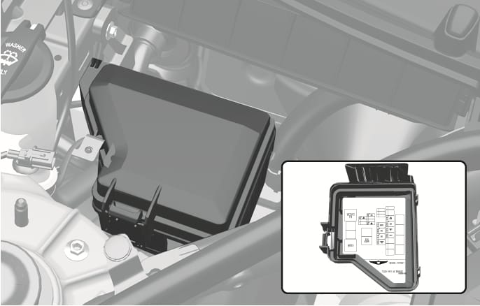
2C_EngineFuseLabel
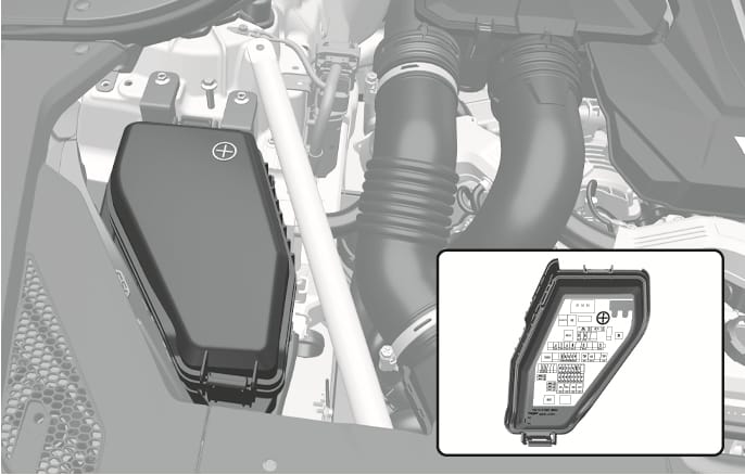
Inside the fuse panel cover, you can find the panel label describing fuse names and ratings.
Not all fuse panel descriptions in this manual may be applicable to your vehicle. When you inspect the fuse panel on your vehicle, refer to the fuse panel label.
1C_EngineFuseLabel_1
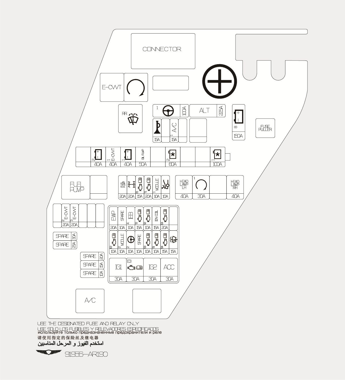
Engine compartment fuse panel (Engine room junction block)
|
Type |
Fuse Name |
Symbol |
Fuse Rating |
Circuit Protected |
|
MINE |
MDPS1 |
|
100 A |
MDPS Unit |
|
ALT |
|
225 A |
Alternator |
|
|
B+8 |
|
150 A |
[RHD] E/R Sub Junction Block |
|
|
MULTI |
B+2 |
|
40 A |
PDC (IPS11, IPS12) |
|
E-CVVT1 |
|
40 A |
E-CVVT Relay (RLY.1) |
|
|
B+1 |
|
40 A |
PDC (Fuse - F36/F46/F48/F26/F38) |
|
|
OIL PUMP |
|
50 A |
Electronic Oil Pump |
|
|
COOLING FAN2 |
|
60 A |
Cooling Fan Motor (G4KR) |
|
|
COOLING FAN1 |
|
100 A |
Cooling Fan Motor (G6DS) |
|
|
SB |
HEAD LAMP LH |
|
40 A |
Head Lamp LH |
|
START |
|
30 A |
Start Relay (RLY.2) |
|
|
HEAD LAMP RH |
|
40 A |
Head Lamp RH |
|
|
MICRO |
FUEL PUMP |
|
20 A |
Fuel Pump Relay (RLY.4) |
|
AWD |
|
20 A |
AWD ECU |
|
|
ECU1 |
|
15 A |
ECM |
|
|
TCU1 |
|
20 A |
TCM |
|
|
MODULE1 |
|
10 A |
Active Air Flap Module |
|
|
ACTIVE HOOD |
|
10 A |
Active Hood Lift Control Module |
|
|
HORN |
|
15 A |
PCB Block (Horn Relay) |
|
|
A/C1 |
|
15 A |
A/C Relay (RLY.5) |
|
|
E-CVVT2 |
|
20 A |
ECM(G4KR) |
|
|
E-CVVT3 |
|
20 A |
ECM(G4KR) |
Engine compartment fuse panel (PCB junction block)
|
Fuse Name |
Symbol |
Fuse Rating |
Circuit Protected |
|
IG1 |
|
30 A |
IG1 Relay |
|
ECU3 |
|
30 A |
Engine Control Relay |
|
IG2 |
|
30 A |
IG2 Relay |
|
ACC |
|
30 A |
ACC Relay |
|
ECU2 |
|
10 A |
ECM |
|
MODULE2 |
|
10 A |
Smart Cruise Control Radar, Front Radar LH/RH, AWD ECU |
|
MDPS 2 |
|
10 A |
MDPS Unit |
|
SENSOR3 |
|
10 A |
[G4KR] Oxygen Sensor (Up/Down) [G6DS] Not Used |
|
SENSOR1 |
|
10 A |
[G4KR] Injector #1~#4, E/R Junction Block (RLY.4) [G6DS] Injector #1~#6(MPI), E/R Junction Block (RLY.4) |
|
SENSOR4 |
|
15 A |
Cooling Fan Motor |
|
WASHER |
|
15 A |
Washer Relay, E/R Junction Block (RLY.3) |
|
EWP |
|
20 A |
Electric Water Pump |
|
IEB4 |
|
10 A |
IEB Unit |
|
TCU2 |
|
15 A |
P/N Relay, TCM, Electronic Oil Pump |
|
SENSOR2 |
|
10 A |
[G4KR] E/R Junction Block (RLY.5), Oil Control Valve (Exhaust), Oil Pump Solenoid Valve, Purge Control Solenoid Valve,RCV Control Solenoid Valve, Canister Close Valve [G6DS] E/R Junction Block (RLY.5), RCV Control Solenoid Valve #1/#2, Purge Control Solenoid Valve, Oil Pump Solenoid Valve, Oxygen Sensor #1~#4, Oil Control Valve #1~#4, Canister Close Valve |
|
IGN COIL |
|
15 A |
[G4KR] Ignition Coil #1~#4 [G6DS] Ignition Coil #1~#6 |
|
ECU4 |
|
20 A |
ECM |
2C_EngineFuseLabel_2
Inside the fuse panel cover, you can find the panel label describing fuse names and ratings.
Not all fuse panel descriptions in this manual may be applicable to your vehicle. When you inspect the fuse panel on your vehicle, refer to the fuse panel label.
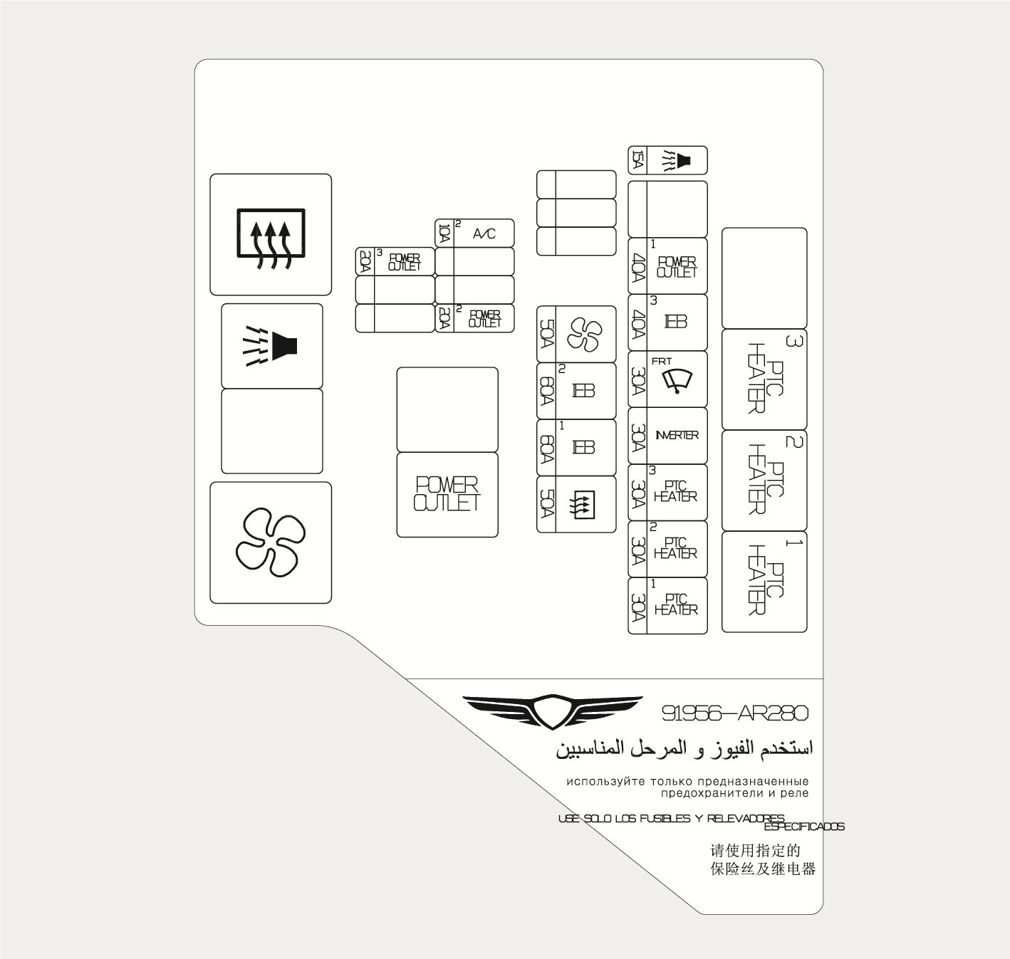
1C_EngineFuseLabel_4
Engine compartment fuse panel (Engine room sub junction block)
|
Type |
Fuse Name |
Symbol |
Fuse Rating |
Circuit Protected |
|
SB |
PTC HEATER1 |
|
30 A |
PTC Heater 1 Relay-LHD (RLY.4) |
|
PTC HEATER2 |
|
30 A |
PTC Heater 2 Relay-LHD (RLY.3) |
|
|
PTC HEATER3 |
|
30 A |
PTC Heater 3 Relay-LHD (RLY.2) |
|
|
INVERTER |
|
30 A |
AC Inverter |
|
|
WIPER FRT |
|
30 A |
Wiper Motor |
|
|
IEB3 |
|
40 A |
IEB Unit |
|
|
POWER OUTLET1 |
|
40 A |
Power Outlet1 Relay (RLY.6) |
|
|
REAR HEATED |
|
50 A |
Rear Heated Relay (RLY.7) |
|
|
IEB1 |
|
60 A |
IEB Unit |
|
|
IEB2 |
|
60 A |
IEB Unit |
|
|
BLOWER |
|
50 A |
Blower Relay (RLY.10) |
|
|
MICRO |
BULGLAR ALARM HORN |
|
15 A |
Burglar Alarm Horn Relay (RLY.8) |
|
POWER OUTLET2 |
|
20 A |
Luggage Power Outlet |
|
|
A/C 2 |
|
10 A |
Front A/C Controller |
|
|
POWER OUTLET3 |
|
20 A |
Front Power Outlet |
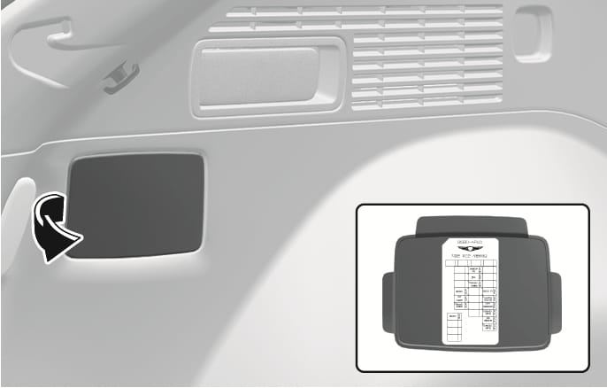
2C_CargoFuseLabel
Inside the fuse panel cover, you can find the panel label describing fuse names and ratings.
Not all fuse panel descriptions in this manual may be applicable to your vehicle. When you inspect the fuse panel on your vehicle, refer to the fuse panel label.
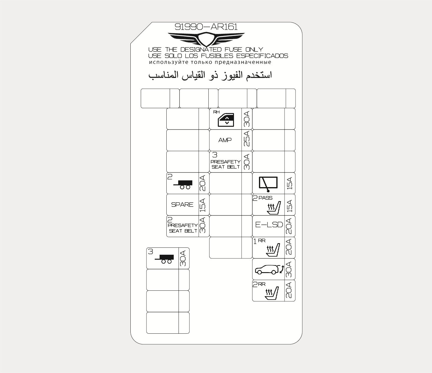
1C_CargoFuseLabel_1
Cargo area (Rear sub junction block)
|
Fuse Name |
Symbol |
Fuse Rating |
Circuit Protected |
|
TRAILER3 |
|
30 A |
Trailer Connector |
|
POWER WINDOW RH |
|
30 A |
Rear Power Window Module RH [LHD] Passenger Power Window Module [RHD] Driver Power Window Module |
|
AMP |
|
25 A |
[W/O ISG] AMP [With ISG] Low DC-DC Converter (AMP) |
|
PRESAFETY SEAT BELT3 |
|
30 A |
Pre-Active Seat Belt Unit |
|
TRAILER2 |
|
25 A |
[W/O ISG] AMP [With ISG] Low DC-DC Converter (AMP) |
|
WIPER RR |
|
15 A |
Rear Wiper Motor |
|
S/HEATER PASS2 |
|
15 A |
[W/O IMS] Passenger Power Seat Module |
|
PRESAFETY SEAT BELT2 |
|
30 A |
Pre-Active Seat Belt Unit |
|
E-LSD |
|
20 A |
E-LSD Control Module |
|
S/HEATER RR1 |
|
20 A |
Rear Air Ventilation Seat Control Module, Rear Seat Warmer Control Module |
|
POWER T/GATE |
|
30 A |
Power Tailgate Module |
|
S/HEATER RR2 |
|
20 A |
Rear Air Ventilation Seat Control Module, Rear Seat Warmer Control Module |
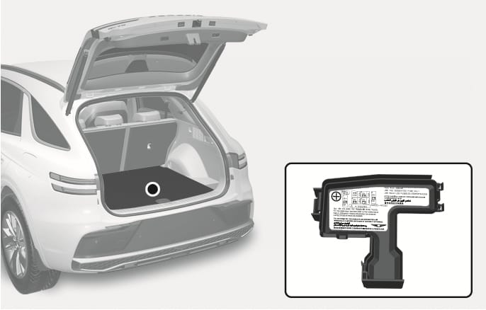
2C_BatteryFuseLabel
Inside the fuse panel cover, you can find the panel label describing fuse names and ratings.
Not all fuse panel descriptions in this manual may be applicable to your vehicle. When you inspect the fuse panel on your vehicle, refer to the fuse panel label.
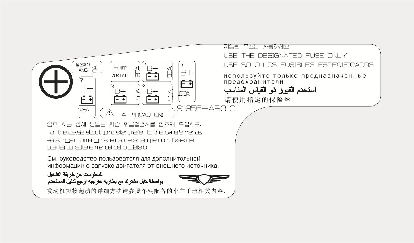
1C_BatteryFuseLabel_1
Cargo area (Battery junction block)
|
Fuse Name |
Symbol |
Fuse Rating |
Circuit Protected |
|
AUX BATT |
|
50 A |
12 V Lithium Auxiliary Battery |
|
B+5 |
|
50 A |
PDC (IPS4, IPS5, IPS6, IPS7) |
|
B+3 |
|
50 A |
PDC (Fuse - F9/F10/F17/F18/F25/F33/F34/F43/F51/F52/F59) |
|
B+4 |
|
50 A |
PDC (IPS13, Long Term Load Latch Relay, Fuse - F4/F5/F12/F13/F20/F21/F37/F54/F55) |
|
B+7 |
|
125 A |
Rear Junction Block (Fuse - S1/F6/F9/F12/F14/F16/F19/F20/ F22/F24/F25/F26) |
|
B+6 |
|
100 A |
E/R Junction Block |
|
AMS |
|
10 A |
Battery Sensor |